 |
Boston
- LM76
Newsroom
The Boston Museum of Fine Arts (MFA) has to move
articles of antiquity
from one location to another. In this instance, they are
moving a 5000 year old relief (hieroglyphics) weighing
8000 pounds to a new location in the Museum.
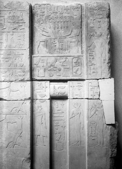
Here is a frontal photo of the Relief from The
Tomb of Senenuka.
Part of wall from tomb of Senenuka; nine stones fitting
together and including two
niches; lower left piece smooth limestone; upper far
left preliminary black ink sketch;
right of this sketch is a complete relief showing two
seated figures; central piece has
large scene of seated male on the left and other smaller
male figure to the right; upper
far right male figure relief outline; left of this again
a scene of two seated figures
at a table.
Senenuka
Time of Khufu or Khafre (Maybe Dyn 5?) Overseer of the
Pyramid-town of Khufu, Director of King’s wad-priests,
Boundary official of a settlement, etc.
The MFA contracted CBI
Consulting of Boston to design
the frame and fixturing.
Craig Barnes, an
award winning architectural engineer
called Mike Quinn of LM76
to review the application. Over the course of several
weeks, LM76 and design
partner Todd Kanipe designed a telescoping, high
load roller/rail system
that won approval. According to CBI's Keith Bouchard,
the linear rail system moves very smoothly and so far
meets the expectations of this program."
According to MFA Antiquity Specialist Jean Louis
Lachevere, “All of these moves present
very real dangers to the artifact being
transported. In this case, we have a 8000 pound relief
which already has its problems due to age and the
fact that it is limestone ( limestone is very
vulnerable to the atmosphere ).” Seen from the
front, the relief is straight. From the back, much of
the top back is gone.
Thus,
the back of the relief
has to be plastered so the back is flat.
Pins
are inserted to further reinforce the relief and then it
is tipped on its back. It is then moved to its new
atmospherically controlled display case.
LM76's design is used in the transfer from the
dolly to the mounting rails and restraints in the
display case. This 36” motion is fraught with things
that can go wrong. One of the considerations is the
possibility of an earthquake…any problem conceivable is
taken into account. |


